- Home
- PCB Prototype
- Assembly
- PCB
- Rigid-Flex PCB
- Technology
- PCB Material
- Epoxy Filled Vias
- Heavy copper circuit board
- HDI Micro vias PCB
- Controlled Impedance
- RF & Microwave PCB
- Rigid-Flex Circuit
- Bending And Folding
- Thermally Conductive PCB
- Flex PCB Design Guidelines
- Rigid-flex PCB design guidelines
- HDI PCB design guidelines
- Heavy copper PCB design guidelines
- Flexible PCB design issues
- Flex-Rigid PCB design issues
- Turn-key PCB Assembly design issues
- PCB Trace Width Calculator
- Company
- Quote

-
Rigid-Flex Circuit
Rigid-Flex Circuit

It’s getting harder to fit everything in the box; it’s also getting more costly. One solution promising to help designers meet the size constraints head on is rigid-flex pcb technology, but most design teams try to avoid using rigid-flex PCBs when product cost is an issue. But is it really as expensive as we think?
To begin with, consider the cost of the traditional rigid-cable-rigid PCB assembly to one based on rigid-flex technology. The former construction works well for short-run designs; however, it requires connectors on each board and the interconnect, all of which drive up BoM cost. Additionally, the rigid-cable-rigid design is prone to ‘cold joints’, and reduced service life. In contrast, rigid-flex circuits eliminate these joints, making them much more reliable and able to deliver overall higher product quality and longevity. So while rigid-flex circuit technology is certainly not new, various considerations now make it much more viable – not the least of which is cost.
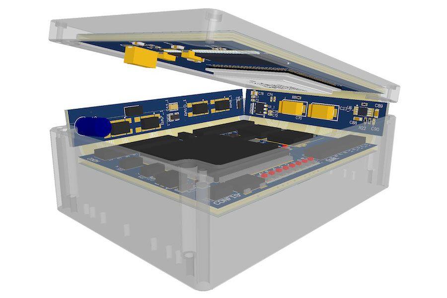
Simulate the rigid flex pcb cost
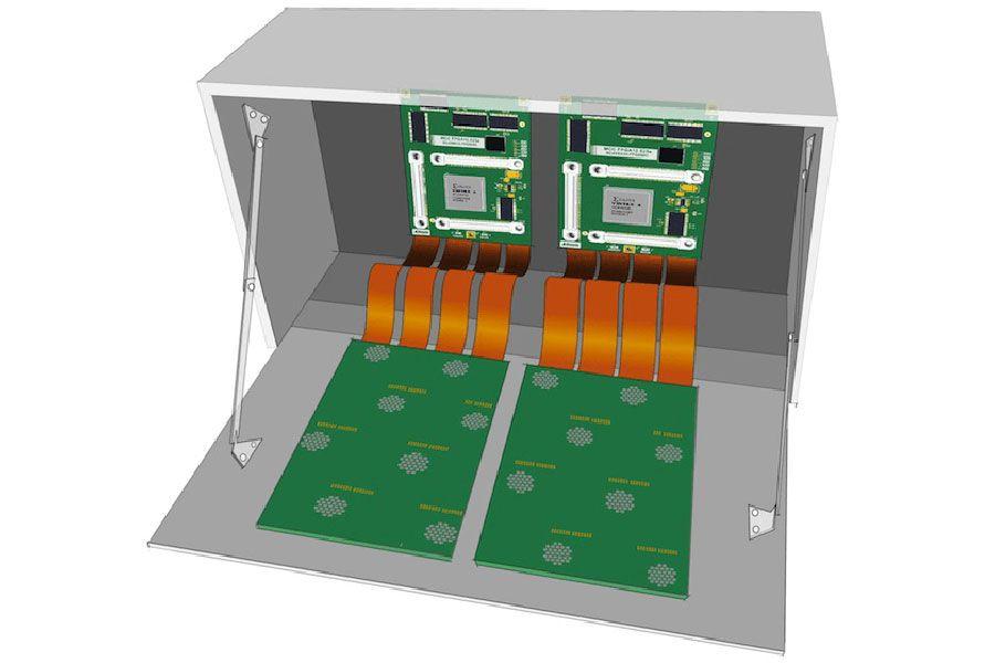
Rigid-flex printed circuit boards are a combination of flexible and rigid substrates laminated into a single package. Rigid-Flex PCBs have been used in the military and aerospace industries for more than 20 years. Due to rigid-flex circuit boards allowing designers to replace multiple PCBs interconnected with connectors, wires and ribbon cables with a single package offering improved performance and reliability. Rigid-Flex circuits have been successfully used for applications in mobile phones and consumer products in the past few years.
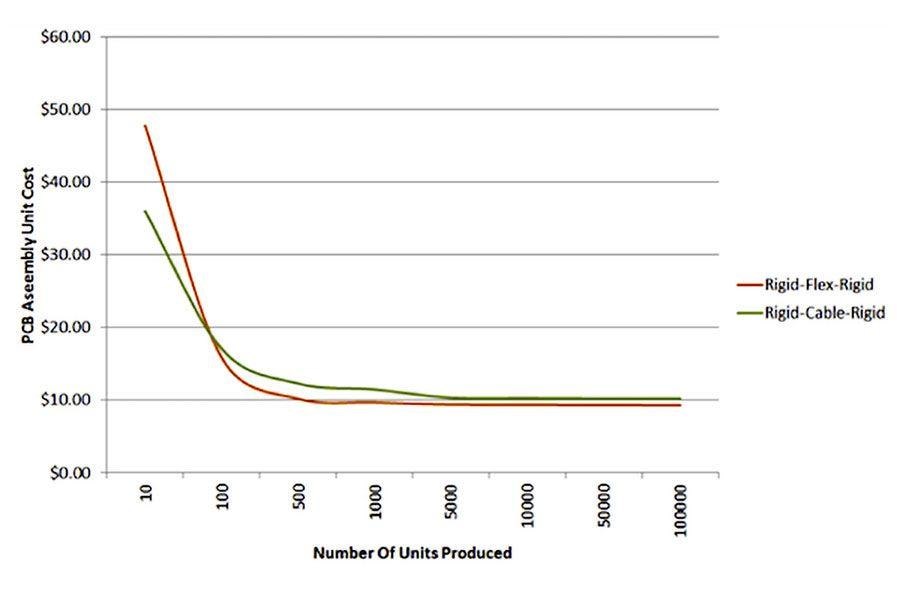
This quote-generated cost plot compares a rigid-flex design to a rigid-cable-rigid assembly.
In some designs, rigid-flex printed circuit boards will not be a viable alternative, and you must do your due diligence in determining the break-even point where the costs are about equal.
This kind of price simulation can be done by considering the total quoted costs for fabrication and assembly. The PCBs can be quoted before the design phase, as long as the parameters of design are well understood (for example, the layer stack, estimated via count, track and space ratios, etc.).
High layer counts are more complex but create high performance and highly reliable PCBs. They have the advantages of reducing emissions, increasing immunity and improving signal quality for high-speed servers, network systems and telecommunication base station equipment to ensure long term reliable infrastructure.
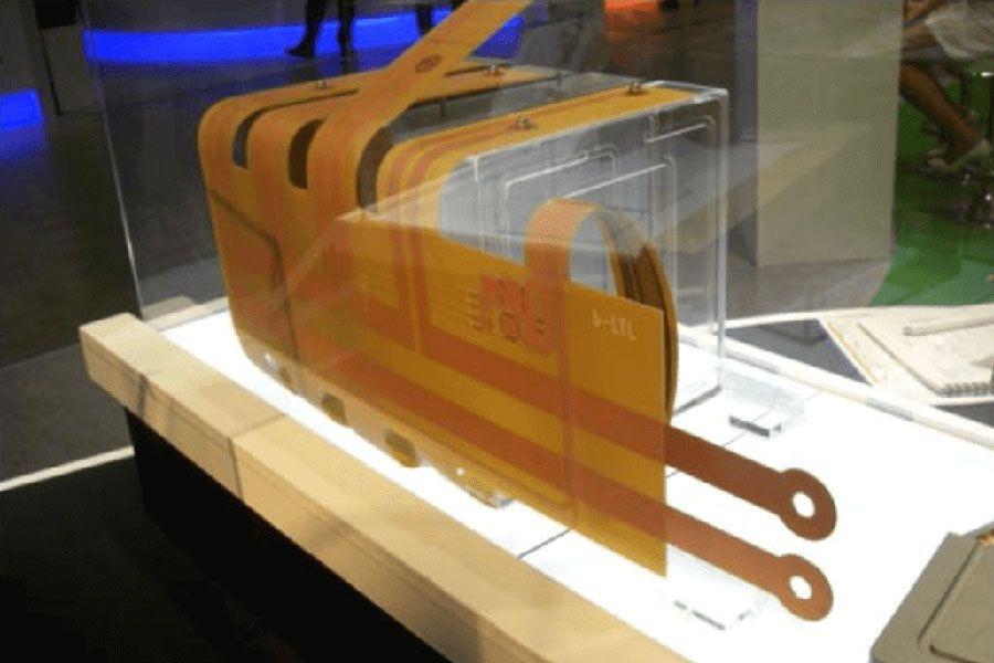
Rigid-Flex PCBs Manufacturer
We performed a manufacturing cost simulation with a real rigid-flex circuit designs and a comparative rigid-cable-rigid equivalent. The component BoMs for comparison differed only in the cable and connectors required for the non-flex version. For our simulation, the traditional design is comprised of four-layer boards that use flexible cable and connectors between them, while the rigid-flex circuit design is a four-layer PCB with two inner flex layers. Manufacturing cost for both designs is based on real PCB fabricator quotes, and includes the cost of assembly.
Find your break-even point
As the project volume depicted in the above picture hits 100 units, the rigid-flex circuit design becomes a more cost-effective option compared to the traditional design approach. A key reason for this cost savings is that rigid-flex circuits do not use connectors/cables or require any connector assembly. Also, they feature increased reliability and process yields. But that’s just the tip of the iceberg.
There are plenty of good reasons to use rigid-flex circuits. They are light, compact, robust, and resilient, and ideal for today’s smaller and more portable electronics. They are ideal for new product designs, but can be used to replace traditional wire harnesses and circuit boards as well. But to realize their full potential, designers must consider the unique requirements of these circuits and the materials they are made of. It is important to recognize that, while the materials that comprise a rigid-flex circuit may be individually flexible, their performance in a completed circuit is greatly impacted by a circuit’s construction.
Because rigid-flex circuits require no cable assembly, their overall assembly effort is reduced, as is their test complexity – both of which drive down cost.
Additionally, fewer components need to be purchased, reducing the supply chain risk. Rigid-flex PCBs can be designed to make product maintenance more convenient and therefore, more cost-effective over the course of the product life cycle.
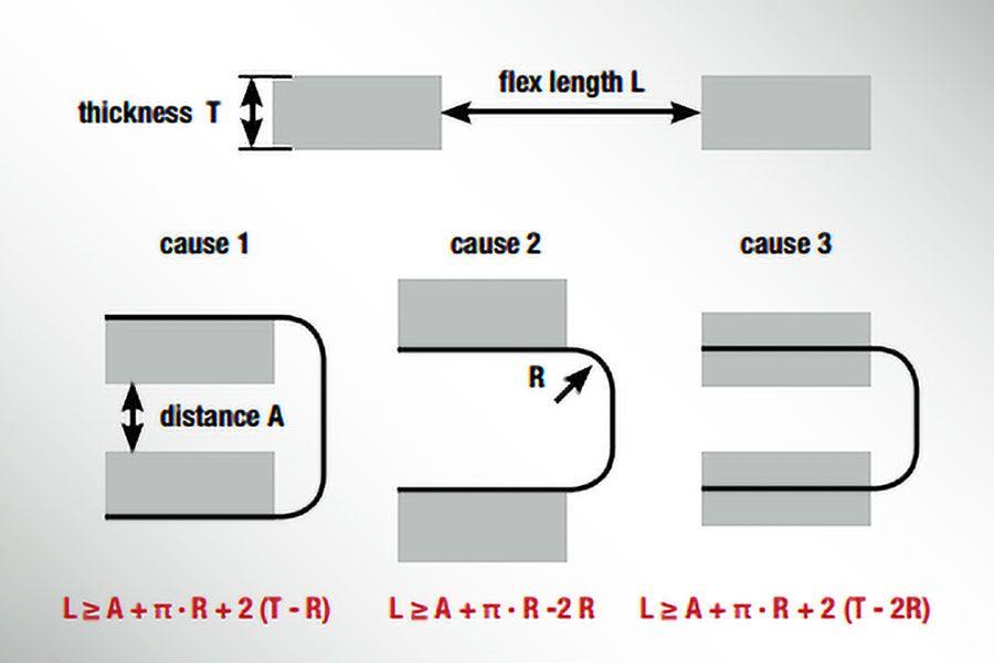
Every rigid-flex circuit has a neutral bend axis. This plane, which is ideally located on the central plane of the material stack, experiences, at least in theory, no compression or tension forces when the circuit is flexed. Toward the outside of the bend, however, outer layers experience increasing tension, which can tear or crack the materials. This can lead to immediate circuit failure or, potentially worse, hairline breaks that will fail after the circuit has been put into service. Toward the inside of the bend, layers are subject to increasing compression. This can cause layers to wrinkle or delaminate, again a potential cause of immediate or eventual failure. Careful design can help prevent these problems.
- Home
- Technology
- Rigid-Flex Circuit
- PCB Technology
- PCB Material
- Epoxy Filled Vias
- Heavy copper circuit board
- HDI Micro vias PCB
- Controlled Impedance
- RF & Microwave PCB
- Rigid-Flex Circuit
- Bending And Folding
- Thermally Conductive PCB
- Flex PCB design guidelines
- Rigid flex PCB design guidelines
- HDI PCB design guidelines
- Heavy copper PCB design guidelines
- Flexible PCB design issues
- Flex-Rigid PCB design issues
- Turn-key PCB Assembly design issues
- PCB Trace Width Calculator
-
Phone:
-
Email:This email address is being protected from spambots. You need JavaScript enabled to view it.


