- Home
- PCB Prototype
- Assembly
- PCB
- Rigid-Flex PCB
- Technology
- PCB Material
- Epoxy Filled Vias
- Heavy copper circuit board
- HDI Micro vias PCB
- Controlled Impedance
- RF & Microwave PCB
- Rigid-Flex Circuit
- Bending And Folding
- Thermally Conductive PCB
- Flex PCB Design Guidelines
- Rigid-flex PCB design guidelines
- HDI PCB design guidelines
- Heavy copper PCB design guidelines
- Flexible PCB design issues
- Flex-Rigid PCB design issues
- Turn-key PCB Assembly design issues
- PCB Trace Width Calculator
- Company
- Quote

-
Thermally Conductive PCB
Aluminum pcb
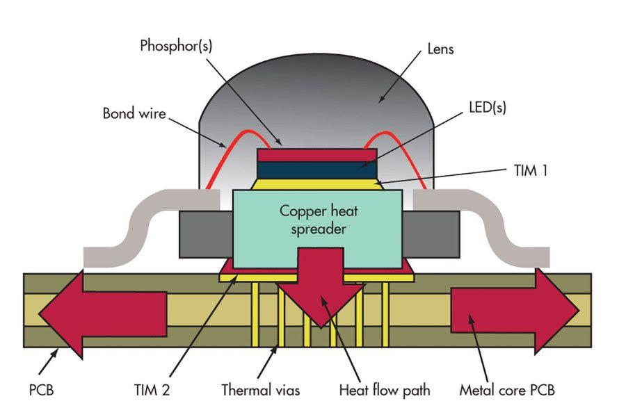
PCB substrates designed for thermal management have been around for a number of years, traditionally servicing power-related applications; however, there are now many more suppliers and substrates emerging to meet the growing demand from LED lighting products. The LED package emits light forward and any excess heat is designed to be dissipated from the base of the component, usually through a bespoke thermal pad or through either the anode or cathode pads. Like other electronic components, the failure rate of an LED doubles with every 10°C increase in junction temperature. So based on the fact that reliability and longevity are key requirements for the successful uptake of LED lighting, good thermal management is an essential element in this growth.


A wide range of available LEDs put varying thermal demands onto the PCB substrate. Low-wattage (0.25W LEDs) and low-density applications are typically dealt with by using standard, single-sided FR-4 or CEM PCBs, where all the heat must be dissipated at the surface and the thermal performance is enhanced by using large copper lands (for heat spreading) and higher copper weights when required. The FR-4/CEM materials are very good thermal insulators and so obtain little or no benefit from a secondary heat sink and the operating temperature is directly influenced by the ambient temperature and although this does limit the use of this technology, it still represents a significant part of the LED market. It should be noted that there are some new FR-4/CEM style laminates that have been developed with a higher thermal conductivity, which allow the LEDs to benefit from secondary heat-sinking.
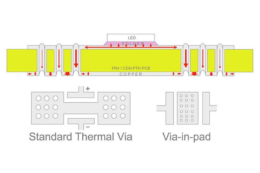
For mid-power (1.0W LEDs), moderate density applications, where the thermal requirements are beyond the capability of a standard, single-sided PCB, the next level of thermal performance comes from FR-4 PTH PCBs using thermal vias to enhance heat dissipation. The heat generated by the LED spreads across the pad and then down the plated via holes to a large copper area on the other side of the board, this heat can then be dissipated into a secondary heat sink. The holes around the LED pads do limit the potential LED density, and from our experience we find that holes placed further than 5 mm from the LED have a much reduced effect on the junction temperature. Obviously, the use of via-in-pad technology will allow for higher LED packing densities but this does create other assembly issues (and if this means using hole-filling, then any cost-savings for using FR-4 will be eroded); however, via-in-pad will improve the thermal performance when compared to having vias around the LED.

To obtain the maximum thermal performance from this PTH approach will require the use of an isolating thermal interface material (TIM), which will eliminate the risk of electrical leakage and help considerably with heat dissipation (into a secondary heat-sink). Ideally, the non-LED side should have no solder resist coating as this provides the best transfer of heat (i.e., using the TIM to provide the electrical isolation); however, many applications use a solder resist in order to ensure the PCB is electrically isolated from the heat sink.

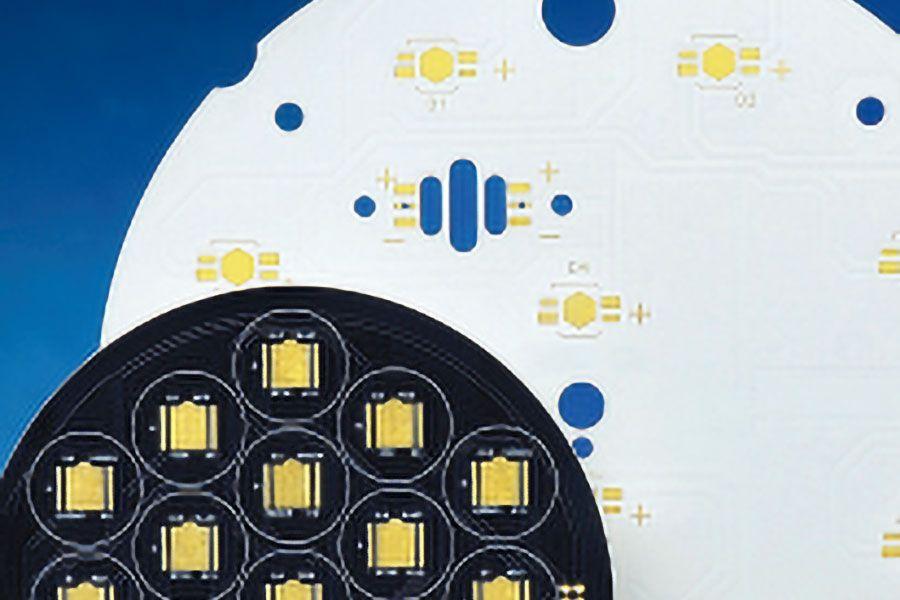
When it comes to mid- to high-power or high-density LED applications, many companies turn to insulated metal substrates (IMS) because it provides a convenient and reliable thermal solution as it comes with an in-built heat-sink. The IMS is a relatively simple material which comprises of a copper foil bonded to a metal base with a thin dielectric. The copper foil provides the circuit image, and because the heat dissipation is primarily routed directly through the dielectric, then the copper weight is less of an issue (as with FR-4 products) and this helps when tracking high-density designs. The metal base is usually aluminium because of its light weight and relatively low cost, and because it is a well-established heat-sink material (thermal conductivity 140–200 W/mK, depending on the grade). For more demanding applications, copper is used (thermal conductivity ~400 W/mK) even though it is heavier and more expensive. It is in the dielectric layer where we see the main difference between suppliers (and their product range), although they all tend to be thin layers (sub 0.20 mm) with a varying level of thermal properties. Typically, the thermal performance of these dielectrics is enhanced by the addition of ceramic materials (such as aluminium oxide, aluminium nitride and boron nitride), increasing the thermal conductivity of the base resin from around 0.25W/mK to upwards of 5W/mK.
What is IMS board
Insulated Metal Substrate (IMS)
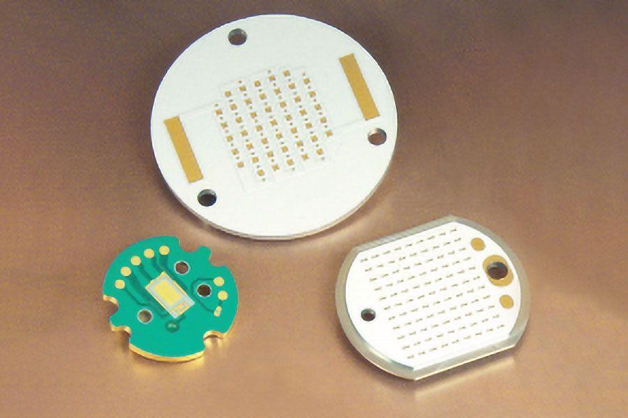
The use of IMS circuit boards for simple single-layer circuits is a special but very effective method of heat dissipation for components across circuit boards. These generally consist of aluminium supports, insulation layers and copper foil. The base materials are available in different design versions.
Aluminum pcb Applications:
- LED technology: Illuminated signs, displays and lighting
- Automotive industry: LED headlights, engine control and power steering
- Power electronics: DC power supply, inverters and engine control
- Switches and semi-conductor relays
Aluminum pcb Manufacturing process
1. The copper foil is laminated onto the metal carrier using prepreg
2. The copper foil is structured
3. Solder mask is applied
4. Surface finish
5. Mechanical processing
Hemeixinpcb offers the following Aluminum pcb special features:
- Materials with prepreg or thermally conductive resins
- Thermal conductivity in the 0.35-8.0 W/(m•K) range
- Scored or routed versions
- White or black solder resist
- Based on highly reflective aluminium
- Special surfaces are possible, such as ceramic surfaces
In the single side printed circuit board business, Hemeixinpcb focuses on IMS boards. These are used primarily as heat sinks for LEDs and power components. To enable heat dissipation, the base material used has one side that is an aluminium or copper layer either 1.0mm or 1.6mm thick.
- Home
- Technology
- Thermally Conductive PCB
- PCB Technology
- PCB Material
- Epoxy Filled Vias
- Heavy copper circuit board
- HDI Micro vias PCB
- Controlled Impedance
- RF & Microwave PCB
- Rigid-Flex Circuit
- Bending And Folding
- Thermally Conductive PCB
- Flex PCB design guidelines
- Rigid flex PCB design guidelines
- HDI PCB design guidelines
- Heavy copper PCB design guidelines
- Flexible PCB design issues
- Flex-Rigid PCB design issues
- Turn-key PCB Assembly design issues
- PCB Trace Width Calculator
-
Phone:
-
Email:This email address is being protected from spambots. You need JavaScript enabled to view it.


