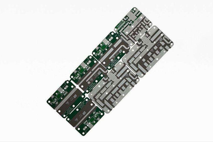
Material requirements of HDI Rigid Flex PCB
The performance of HDI Rigid Flex PCB continues to grow rapidly in the flexible circuit market, while market demand is driving the growth of HDI Rigid-Flex PCB. Faced with the challenges of HDI, leading flexible circuit manufacturers are turning to new materials, improving the style of standard materials, and new production technology.
This article focuses on the material requirements of HDI Rigid-flex PCB and the material of HDI Rigid Flex PCB developed in recent years. The most significant applications for HDI Rigid Flex PCB growth are in mobile phones and other handheld communications and computer equipment (such as PDA), other high-growth applications include Tape-flex boards for chip packaging, suspension flex circuits for hard drives, and interconnects, flexplates for flat displays, As well as the flexible circuit of inkjet printer Cartridges. For nearly more than 10 years, many HDI Rigid Flex PCB materials have been developed to meet the needs of HDI design and application, such as high-performance basement membranes, non-adhesive substrates, Liquid pi resins, and photosensitive coatings. HDI applications require finer lines and small guide holes, so thinner conductor layers and substrates are required for rigid Flex PCB production, while the physical properties of thin substrates are often difficult to meet technical requirements. The thin material will affect the performance and yield of the FPC, and the dimensional stability of the material in the production of HDI Rigid Flex PCB is a major factor affecting the yield of the Product. It is necessary to solve the contradiction between material, structure and production processes in order to obtain high-density circuit products. In addition, the electrical transfer in the flexible circuit is a phenomenon that causes the circuit to be destroyed, there are some types of flexible circuit binder when in the wet, the temperature rises and the bias voltage, the copper ions in the electric route can be moved through the binder so that the positive and negative between the anode to connect a line. When the ions begin to arrange between copper conductors, the filaments begin with a dendritic or lightning-like shape, and in extreme cases the wire is connected to a certain thickness between the two lines, causing a short circuit.
One of the main ways to achieve HDI’s flex circuit is through the use of thin, fine-grained and Low-profile copper foil, standard copper foil for conventional flex circuits is typically 1oz (35μm), 1oz copper Foil can provide the right performance for normal density graphics, but for HDI applications, Most manufacturers use 1/2oz (18μm), 1/3oz (12μm), or even 1/4oz (9μm) copper Foil. In the HDI Rigid-Flex PCB, The most important is to make small windows (and possibly close to each other), and to ensure that the window is laminated without being filled by the binder, so that the exposed copper is covered, so selecting the covering material for HDI must tightly control its flow performance. Too little liquidity creates voids between fine lines and reduces electrical insulation; too much liquidity will cover the WINDOW. Not all flexible binders have this performance, similar to the “low-fluidity” semi-cured sheet in rigid plate Fabrication. The manufacturer must select the appropriate covering film and choose the appropriate lamination process based on the fluidity of the Binder.
You can get more information about Controlled Impedance to log in to – www.hemeixinpcb.com or call us at +86 0755-27586529 you can mail us at This email address is being protected from spambots. You need JavaScript enabled to view it.


