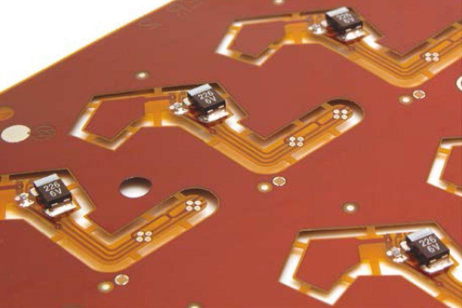
Rigid flexible circuit
For the 6 layers rigid-flexible circuit, we at Hemeixinpcb provide 2 layers of flexible circuit stiffeners for additional support. These flexible circuit stiffeners reinforce the areas of the PCB that comprise flexible circuitry. They are designed to support the various components on the board, thus increasing the PCB’s durability. They are especially useful in the mounting of the rigid-flexible circuit PCB in an application. The flexible circuit stiffeners can also be used to perform specific functions such as heat dissipation and strain relief. At Hemeixinpcb, we provide flexible circuit stiffeners for single as well as double-sided boards. We can provide stiffeners on the top as well as bottom side of the flexible circuit. We can custom design the thickness of the stiffener as per your requirements.
- Stiffeners are an inexpensive option for rigidizing pin areas, surface mount areas, or hole patterns for component mounting (provided SMT components are on one side only). Surface mount areas do not always require a stiffener, depending on component size, but a stiffener is recommended and will add very little to cost or bulk.
- Stiffeners can be utilized to force a bend line in selected areas. Hemeixinpcb can provide epoxy fillets for the edges of the FR-4 stiffener, where flexing occurs.
- Stiffeners reinforce solder joints and increase abrasion resistance.
- Circuits may be attached to a stiffener pallet (multiple parts) to provide easier handling for automated pick-and-place and component soldering. Circuits can be held together for processing on the pallet, then singulated (clipped free) after wave soldering and circuit testing.
- Stiffeners can be marked with component mounting locations for rapid assembly.
- Stiffeners are commonly FR-4 or polyimide material. They are usually applied with modified acrylic adhesive.
- Standard FR-4 material thicknesses range from 0.003″ (0.08mm) to 0.125″ (3.18mm). A typical thickness for polyimide stiffeners is 0.005″ (125μm), but 0.001″ (25μm), 0.002″ (50μm), and 0.003″ (75μm) are also available. Polyimide stiffeners are less expensive than FR-4 stiffeners because they are punched on a die instead of routed with a drill bit. The polyimide stiffener lay-up procedure is performed with alignment pins, therefore, registration is better. The polyimide stiffeners are trimmed with the cover on the final blanking procedure, which guarantees perfect outside alignment.
- When using multiple stiffeners, maintaining the same stiffener thickness consistent throughout the entire construction can help lower costs.
Flex layer core thickness plays an important role, as does keeping the same finish thickness on all rigid areas. As for rigid circuitry, you want to avoid having 32 mils on one side and 62 on the other, for example, otherwise the sequential lamination process of rigid-flexible circuit fabrication comes into question and poses difficulties, so it’s prudent to keep the same finish thickness in all rigid areas.
Normally, in a rigid board, you have even number of layers. By comparison, in a flexible circuit board you can have even and odd numbers. For example, you could have six layers on the rigid side but only three layers on the flex side.
Layer construction when designing the flex is also very important. You have to make sure you are minimizing the thinnest possible construction for the bend radius to improve flexibility. If you have a five-mil Kapton material versus two-mil Kapton, flexibility and bend radius will be better for the two-mil Kapton.
Also, when designing rigid-flex circuitry, you have to ensure both flexibility and mechanical reliability. You have to take into account the fine balance that comes with experience to make sure that the board is designed is flexible enough to perform its function and reliable enough to endure the flex and bend cycles that are being calculated for its life cycle. Normally, you use half-ounce copper for flex boards. In extreme cases, when high capacity is required, you can use one ounce, but this is the exception, not the rule.
One thing you need to do is perform a paired structure. For example, if you’re working with an eight-layer rigid board, you can have four flex layers or two layers of flex circuits.
Also, it’s best to try to offset the traces from layer to layer in the bend area. This is because multiple traces going into the bend area jeopardize the flex circuitry over the long term when it is flexing and bending an inordinate number of times. If there is an offset, then all the stress and strain is not concentrated at one point but is instead distributed throughout the circuitry. This means the stress and bend area are considerably more flexible and reliable over a longer period.
When it comes to impedance controlled design, sometimes offsetting trace layers may not be possible. The reason for this is you need to have the trace in the proximity of a solid reference plane, which may not allow you to implement an exact offset of traces. Impedance controlled design may make it challenging to maintain staggered traces, which directly affects mechanical flexibility and reliability.
What can be done is to offset impedance controlled traces with subsequent layers. For example, you can run one trace on layer 3, you can run the reference plane on layer 4, and you can run the other matching staggered trace on layer 5. Thus, you can offset the traces between different layers, but you still need to keep the reference plane in mind because impedance is a function of the signal’s distance from the reference plane.
Offsetting impedance control traces with subsequent layers is but one of several design considerations that need to be factored in when creating a flex circuit-based wearable and/or IoT design. The points elaborated on in this article are the major ones that need to be considered, including bend radius, bend ratio, strains created at different locations, and via placement. However, as you move along in your designs, you’ll find others to factor in depending on whether you are targeting a consumer, industrial, military/aerospace, or medical electronics application.


