What is Rigid-Flex Circuit?

WHAT IS RIGID-FLEX PCB?
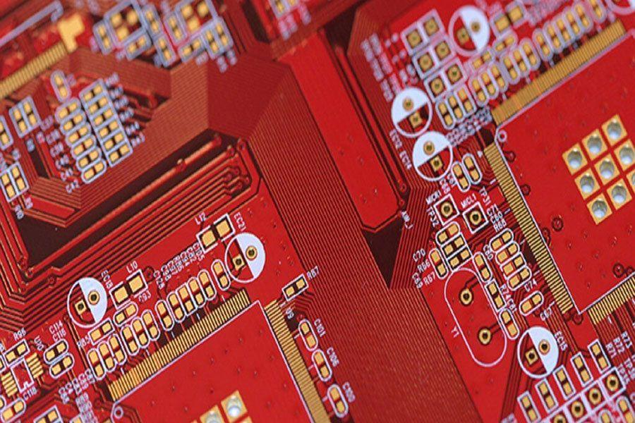
As the name suggests, a flexible printed circuit is a pattern of conductors printed onto a flexible insulating film. Rigid-flex PCB is the name given to a printed circuit that is a combination of both flexible circuit(s) and rigid circuit(s), as shown in the image above. This combination is ideal for exploiting the benefits of both flexible and rigid circuits – the rigid circuits can carry all or the bulk of the components, with the flexible sections acting as interconnections between the rigid sections.
Flexible circuit technology was initially developed for the space program to save space and weight. They are popular today as they not only save space and weight – making them ideal for portable devices such as mobile phones and tablets – they can also: reduce packaging complexity by substantially reducing the need for interconnect wiring; improve product reliability due to reduced interconnection hardware and improved assembly yields; and reduce cost, when considered as part of the overall product manufacture and assembly costs.
Flexible circuits are normally divided into 2 usage classes: static flexible circuits, and dynamic flexible circuits. Static flexible circuits (also referred to as use A) are those that undergo minimal flexing, typically during assembly and service. Dynamic flexible circuits (also referred to as use B) are those that are designed for frequent flexing; such as a disk drive head, a printer head, or as part of the hinge on a laptop screen. This distinction is important as it affects both the material selection and the construction methodology. There is a number of layer stack-up configurations that can be fabricated as rigid-flex, each with their own electrical, physical and cost advantages.
A rigid-flex design does not have a consistent set of layers across the entire circuit design, the rigid section of the board will have a different set of layers from the flexible section. And if the rigid-flex design has a number of rigid sections joined by a number of flex sections, then there may be a different set of layers used in each of these sections. A PCB editor with a single layer stack cannot support this design requirement. To support this, In rigid-flex packaging, a flexible circuit substrate provides a backbone of wiring with rigid multiplayer circuit sections built-up as modules where needed., as shown below.
The Layer Stack Manager supports the definition of any number of layer stacks.
When to use a rigid-flex circuit board?
It’s getting harder to fit everything in the box; it’s also getting more costly. One solution promising to help designers meet the size constraint head-on is rigid-flex PCB technology, but most design teams try to avoid using rigid-flex PCBs when product cost is an issue. But is it really as expensive as we think?
To begin with, consider the cost of the traditional rigid-cable-rigid PCB assembly to one based on rigid-flex technology. The former construction works well for short-run designs; however, it requires connectors on each board and the interconnect, all of which drive up BoM cost. Additionally, the rigid-cable-rigid design is prone to ‘cold joints’, and reduced service life. In contrast, rigid-flex circuits eliminate these joints, making them much more reliable and able to deliver overall higher product quality and longevity. So while rigid-flex PCB technology is certainly not new, various considerations now make it much more viable – not the least of which is cost.


